-
Products
-
-
IPS TFT LCD Display
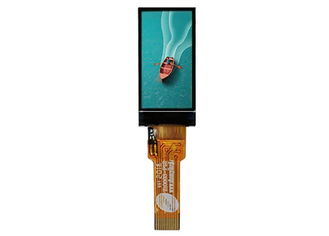
- Z15007 1.47 inch LCD Module SPI Interface ST7789P3 Controller 172x320 IPS Screen
- Z20007 2 inch Landscape Display 320x240 LCD Panel SPI+RGB Interface ILI9342C Controller
- Z28012 2.86 inch LCD Display 376x960 IPS View Angle ST7701 Controller
- Z28018 High Brightness Circular Display 2.8 inch 480x480 Resolution IPS View Angle
- Z30090 3 inch 282x960 TFT LCD Display MIPI Interface ST7701 Driver IC
- Z34014 3.4 inch Incell LCD panel Bar Shape 540 x 960 Resolution MIPI Interface JD9920T Controller
- Z35033 3.5 Inch 480x800 TFT LCD Module SPI+RGB Interface ST7701S Driver IC
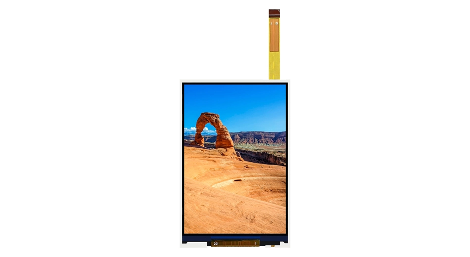
- Z40063 4 inch SPI LCD Display 320x480 Vertical Screen ST7365P Controller IPS View Angle
- Z40067 4 inch Incell LCD Module MIPI Interface 480x1080 Pixels Stretched Bar Display
- Z40072 High Brightness Square Display 4 inch 720x720 MIPI Interface LCD Module Sunlight Readable
- Z43038 480x272 4.3 inch SPI Interface Display LCD Display NV3041A Controller
- Z50075 High Brightness 5 inch Square Display 600x600 Resolution MIPI Interface OTA7290B Controller
- Z70120 Square 7 inch 750x750 LVDS Interface TFT LCD Panel 1500nits Brightness
- Z283001 2.83 Inch 400x800 Incell LCD Display Built-in Multi Point Touch MIPI Interface
- Z104X1-G10A High Brightness 10.4 inch LCD Module 1024x768 Resolution LVDS Interface
- Z20004 2 inch 480x360 Landscape LCD Display Sunlight Readable MIPI Interface with Metal Frame
- Z17002 1.69 inch 240*280 SPI Interface LCD Screen ST7789P3 Controller TFT Display
- Z20005 High Temperature Automative Grade 2 inch 170x320 LCD Display MCU Interface 600 cd/m2
- Z27001 2.7 inch 960x240 Horizontal LCD Screen TFT Type SPI RGB Interface ILI8961 Controller
- Z27002 2.7 2.8 inch Square LCD Display TFT 320x320 MIPI Interface ILI9488 Controller Screen Module
- Z40059 4 inch SPI LCD Display 320x480 Vertical Screen ST7365P Controller IPS View Angle
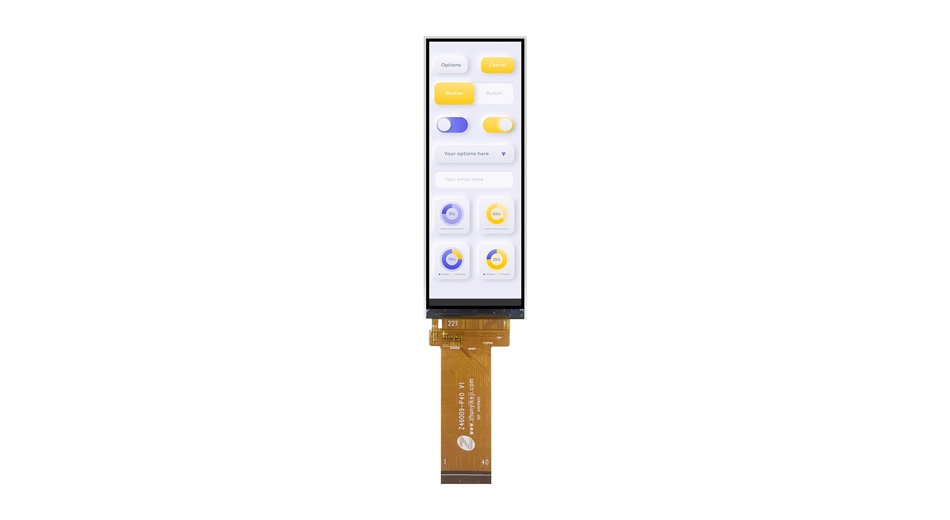
- Z46009 4.6 inch Untra Wide Stretched LCD Display 320x960 ST7701 MIPI Interface Bar Screen
- Z70086 7 inch IPS LCD Panel 800*480 QVGA 50PIN RGB Interface TFT Type
- Z121001 High Brightness 12.1 inch LCD Display 1800nits 1280*800 TFT Screen LVDS Interface
- Z10003 0.96 Inch LCD Display 128*64 4 Lane SPI Interface
- Z13006 1.3 inch Round IPS LCD Display 240*240 24pin SPI Interface GC9A01 Driver IC
- Z13001-P24 1.3 Inch LCD Screen 240x240 8 Bit MCU Interface
- Z13001 240*240 1.3 Inch TFT LCD Display 4 Wire SPI Interface 500nits
- Z13002 1.3 Inch 240*240 LCD Display IPS IC ST7789V SPI Interface
- Z13004 1.3 Inch 240*240 IPS LCD Module SPI Interfae ST7789V Controller
- Z147001 1.47 Inch 172*320 Bar LCD Display with SPI Interface ST7789T3 Controller
- Z15002 1.5 Inch Square LCD Display Screen with MCU Interface 240*240
- Z154001 1.54 inch SPI MCU Interface 240*240 IPS LCD Display ST7789T3 Driver IC TFT Type
- Z16003 Small 1.6 inch Circular TFT LCD Display ST77903 Driver IC 16PIN SPI Interface
- Z169001 Hot Sale 1.69 Inch 240*280 LCD Display SPI Interface
- Z18001 1.8 Inch 128*160 LCD Display Panel 8-bit MCU Interface
- Z20001 240*320 2 Inch LCD Display Module MCU/SPI Interface 25PIN
- Z21001 480*480 2.1 Inch LCD Module Display MIPI Interface 30PIN IPS View
- Z21002 2.1 Inch Circular LCD Screen Display with 480*480 SPI+RGB Interface
- Z24006 2.4 Inch TFT Display 240*320 MCU Interface ST7789V
- Z24008 2.4 Inch IPS LCD Display 240*320 MIPI Interface
- Z28001 2.8 Inch IPS LCD Display 240*320 Full View MCU Interface ST7789V IC
- Z28005 TFT LCD Screen 2.8 inch 240*320 Resolution IPS View Angle ILI9341V Controller SPI/MCU
- Z28007 2.8 inch Round LCD Display 480*480 TFT Type SPI+RGB Interface IC ST7701S
- Z30010 480*854 3 Inch TFT LCD Screen 400nits 40PIN RGB+SPI ST7701S Controller
- Z30032 3 Inch TFT LCD Module 40PIN MIPI/SPI+RGB Interface ST7701S Driver
- Z30043 3 Inch LCD Display MIPI Interface ST7701S Driver IC 350 Nits 480*854 QVGA
- Z30052 3 Inch TFT LCD Panel 480*854 12PIN MIPI Interface ST7701S Driver
- Z30054 High Brightness 3 Inch IPS LCD Display 480*854 580 Nits MIPI Interface ST7701S
- Z30056 TFT Type 3 Inch Display Module 480*854 QVGA 22PIN MIPI ST7701S Controller
- Z30060 3 Inch IPS LCD Screen QVGA 480*854 420 Nits 30PIN MIPI Interface ST7701S IC
- Z30074 3 Inch TPS LCD Module 40PIN RGB+SPI 480*854 520 Nits ST7701S Driver IC
- Z30078 3 Inch IPS Display Screen RGB+SPI Interface ST7701S Driver 480*854 QVGA
- Z30079 3 Inch 480*854 LCD Screen IPS View Angle 24PIN MIPI JD9161Z Controller
- Z30082 3 Inch TFT Display 480*854 24PIN MIPI Interface JD9161Z Driver
- Z30083 Vertical 3 Inch TFT LCD 480*854 Resolution 24PIN MIPI Interface 500nits
- Z34001 3.4 Inch Square LCD Display Module QVGA 480*480 500nits SPI+RGB/MIPI Interface
- Z34005 3.4 inch Round TFT LCD Screen Panel 800*800 SPI+RGB Inerface Brightness 600nits
- Z35008 Factory Custom 3.5 Inch IPS LCD Panel RGB+SPI Interface 320*480 ST7272A
- Z35013 Custom LCD Module 3.5 Inch 320*240 ILI9488 Controller MIPI Interface
- Z35013-P12 3.5 Inch LCD Display 320*480 12PIN SPI Interface 300 Nits Luminance
- Z35018 3.5 inch 320*480 IPS LCD Screen Panel SPI interface ILI9488 Controller from Factory
- Z35030-P25 3.5 Inch TFT LCD Module 480*800 25PIN MIPI Interfae ST7701S IC
- Z35030-P40 3.5 Inch TFT LCD Screen 480*800 40PIN SPI+RGB Interface ST7701S Driver
- Z35101 3.5 Inch 640*480 LCD Display 450nits Full View NV3052C Controller RGB Interface
- Z37001 3.71 Inch 240*960 LCD Display IPS View 45PIN SPI+RGB Interface ST7701S Controller
- Z40032 4 Inch 480*800 TFT Display SPI+RGB Interface 40PIN LCD Screen Factory
- Z40035 4 Inch LCD Display TFT Type 40PIN MIPI Interface ST7701S Controller
- Z40050 4 Inch Custom LCD Panel 720*720 MIPI Interface Square Style ST7703 Controller
- Z40045 4 Inch IPS LCD 480*800 Display Screen JD9161Z IC Full View MIPI Interface
- Z40046 4 Inch LCD Screen 480*800 400nits Brightness JD9161Z Driver 40PIN MIPI
- Z40053 4 Inch TFT LCD Display QVGA 480*800 MIPI/SPI+RGB Interface
- Z43014 4.3 Inch TFT LCD Horizontal 480*272 40PIN RGB Interface ST7283 Driver
- Z43016 4.3 Inch 480*272 LCD Module Screen 500nits ST7283 Controller RGB Interface
- Z43017 Hot Sale 4.3 Inch LCD Display 480*272 QVGA 40PIN RGB Interface ST7283 IC
- Z43018 4.3 Inch IPS LCD Display 480*272 40PIN RGN Interface SC7283 Driver IC
- Z43021 4.3 Inch TFT LCD Module 480*272 ST7283 Controller 40PIN RGB Interface
- Z43027 4.3 Inch 3D Printer LCD Screen MIPI/RGB+SPI GC9503V Controller QVGA 480*800
- HXH43029 600 Nits 4.3 Inch TFT LCD Screen 480*272 40PIN RGB Interface SC7283-G4 Controller
- Z43080 4.3 Inch TFT LCD Display 800*480 Resolution 1000nits RGB Interface
- Z45058 4.5 Inch LCD Module TFT Type 480*854 MIPI Interface 20PIN
- Z45059 LCD Factory Custom 4.5 Inch 480*854 Dispaly Screen IC JD9161Z MIPI Interface
- Z40067 4 inch Incell LCD Display integrated Touch Screen 480*1080 MIPI interface Cutting-edge
- Z49399 500nits 5 Inch 480*854 TFT Display Screen ST7701S Controller RGB+SPI Interface
- Z49416 5 Inch 480*854 POS LCD TFT Display JD9161Z Controller MIPI Interface
- DM49417 5 Inch LCD Screen 480*854 TFT Type MIPI Interface JD9161Z-JN Controller
- Z49420 5 Inch LCD Display 720*1280 30PIN MIPI Interface 320 CD/M2
- Z49421 5 Inch 720*1280 Display Module 30PIN IPS View GH1001 Driver IC MIPI Interface
- Z50070 5 inch 800*480 Horizontal IPS LCD Display
- Z55290 5.5 Inch TFT LCD Display 720*1280 420 Nits 31PIN MIPI Interface
- Z55292 720*1280 5.5 Inch IPS LCD Screen 31PIN MIPI Interface JD9365DA-H3 Controller
- Z57003 320*240 5.7 inch TFT LCD Display MIPI Interface JD9168S IPS View Angle 1300nits
- Z57011 High Brightness 5.7 inch IPS LCD Screen Panel 640*480 MIPI Interface JD9168S
- Z686006 Bar Type 6.86 Inch LCD Screen Panel 480*1280 Full View Angle MIPI Interface
- Z69001 Vertical Screen 6.9 inch 720*1440 IPS LCD Display MIPI Interface JD9168S
- CD0695025LCD 6.95 Inch LCD Display IPS View Angle 600*1024 MIPI Interface OTA7290B-C Controller
- CD0695039 7 Inch IPS Display Module 600*1024 MIPI Interface 400nit Brightness
- Z70001 7 Inch 600*1024 TFT LCD Panel MIPI Interface IPS View
- Z70010 7 Inch IPS LCD Display 720*1280 40PIN MIPI Interface ILI9881C Driver IC
- Z70017 1024*600 7 Inch Custom LCD Screen 500nits Double Controller MIPI Interface
- Z70027 7 Inch IPS LCD Screen QVGA 600*1024 380 Nits 40PIN MIPI Interface
- Z70048 7 Inch TFT Display Module 1024*600 50PIN RGB Interface
- Z70049 7 Inch Display Panel 1024*600 LCD Module LVDS Interface Double IC
- Z70069 High Luminance 700nits 7 Inch TFT LCD Module RGB Interface 1024*600 QVGA
- Z70070 7 Inch TFT LCD Screen 1024*600 30PIN MIPI Interface EK79007AD3+EK73217BCGA Driver
- Z70072 Vertical Screen 7 Inch LCD Display 600*1024 30PIN MIPI Interface 350 Nits Brightness
- Z70078 7 Inch Electric Vehicle Display 500nits 1024*600 LCD Screen MIPI Interface IPS View
- Z70079 720P 7 Inch 720*1280 LCD Screen MIPI Interface JD9366AB Driver IC 30PIN
- HL070WSCAV019 7 Inch TFT LCD Display 600*1024 40PIN MIPI Interface IPS View Angle
- Z70085 7 Inch LCD Module 720*1280 ILI9881C Driver IC MIPI Interface IPS View
- Z70103 Sunlight Readable 7 inch TFT LCD Display Panel 1000 cd/m2 IPS View RGB Interface
- Z784001 7.84 Inch LCD Displa 400*1280 OTA7290B Driver IC 4 Line MIPI Inerface 1000 Nits
- Z80008-SPM288 8 Inch 800*1280 IPS LCD Module Full View MIPI Interface 40PIN
- Z80019 High Brightness 500nits 8 Inch LCD Screen 800*1280 JD9365DA IC MIPI
- Z80035-P39 High Definition 8 Inch TFT LCD Display 1200*1920 800nits 39PIN MIPI Interface
- Z80036 TFT LCD Screen 8 inch 1280*800 LVDS Interface Horizontal Display for Taptop Vending Home
- Z88001 Automotive Display 8.8 inch 480*1920 TFT LCD Screen Panel MIPI Interface 550cd/m2 OTA7290B
- PJ8901B01 8.9 Inch LCD Display 800*1280 350 Nits Brightness 40PIN MIPI Interface
- Z90006 9 Inch 800*1280 500nits IPS LCD Screen MIPI Interface TFT Type
- Z90010 IPS View 9 Inch LCD Screen 800*1280 MIPI Interface GH8555BC Controller
- Z90014-SPM308H 9 Inch LCD Module 800*1280 40PIN MIPI Interface GH8555BC Controller IPS View
- Z90018 High Definition 9 Inch 800*1280 LCD Display TFT 30PIN MIPI Interface
- Z90019 9 Inch LCD Display Screen 800*1280 350nits 40PIN MIPI Interface
- Z90080 9 Inch 1024*600 TFT LCD Display 40PIN LVDS 400nits Brightness
- Z101017 HD 7 Inch TFT LCD 1200*1920 QVGA MIPI Interface OTA7290B Controller
- Z101020 LCD Mufacturer Custom 10.1 800*1280 Inch LCD Panel GH8555 IC Driver MIPI
- Z101024 10.1 Inch IPS LCD Display 800*1280 31PIN MIPI Interface
- Z101027 800P 10.1 Inch Custom LCD Display 800*1280 Resolution MIPI Interface
- Z101028 10.1 Inch TFT LCD Screen 1200*2000 Driver IC NT36523 30PIN MIPI Interface
- Z101060-P50 Horizontal Display 10.1 Inch TFT LCD 1024*600 QVGA 50PIN RGB Interface
- Z101080 10.1 Inch 1280*800 TFT LCD Screen 350 Nits LVDS Interface
- Z10100-P45 10.1 Inch 1920*1200 LCD Display 1000nits LVDS Interface Support HDMI
- Z116001 Bar Type 11.6 Inch 1920*1080 IPS LCD Display LVDS Interface TFT
- Z123001 High Brigthless 12.3 Inch 1920*720 Bar TFT LCD Screen Panel FT7251 LVDS Interface
- Z123003 12.3 Inch TFT LCD Display 1920*720 50PIN LVDS 400nits Full View
- Z13005 High Brightness 700nits 360*360 1.3 inch TFT Display SPI Interface JD5858A Controller
- Z14601 High Resolution 360*360 1.46 inch Round TFT LCD Display ST77916 Driver SPI Interface
- Z15004 1.5 Inch 320*320 LCD Panel MIPI Interface Brightness 600cd/m2
- Z40054 4 inch 720*720 LCD Display MIPI Interface 500 cd/m2 Round TFT LCM
- Z50006 Big Size IPS View Angle 5 inch 1080*1080 TFT LCD Screen MIPI Interface HX8399 Driver
- Z60036 6 inch 720*1480 TFT LCD Panel 720*1480 Resolution MIPI Interface
- Z70088 High Brightness 1000 nits IPS View Angle 7 inch TFT LCD Screen 800*1280
- Z70102 FHD 7 Inch 1200*1920 IPS LCD Display MIPI Interface 1000cd/m2 Luminance
- Z80051 720P 8 inch 1280*720 IPS TFT LCD Display LVDS Interface Brightness 800cd/m2
- Z101042 10.1 Inch IPS LCD Panel 1280*800 QVGA LVDS Interface 500 Nits
- Z101044 High Brightness 10.1 Inch TFT Display Moudle LVDS Interface 1280*800 1000nits LCD
- Z103002 Stretched Bar Type 10.25 Inch Ultra Wide LCD Panel 1920*720 Support HDMI Android
- Z104001 Industrial Screen 10.4 Inch 800x600 LVDS TFT LCD Screen
- Z133001 13.3 Inch 1920x1080 TFT LCD Display Edp Interface Full View Angle Full Definition
- Z156003 FHD 15.6 Inch 1920x1080 LCD Display EDP Interface With Metal Frame
- Z170001 17 Inch TFT LCD Sreen 1280x1024 Normal White Display Mode
- Z173001 Full HD LCD Module 17.3 Inch 1920x1080 LVDS Interface Liquid Crystal Display
- Z185001 18.5 Inch 1920x1080 LVDS LCD Screen with Hight Brightness 1000cd/m2
- Z215001 21.5 Inch Monitor Screen 1920x1080 LVDS Interface High Speed TFT LCD
-
TN TFT LCD Display
- Z24009 2.4 Inch TFT LCD Display 400 Nits 20PIN MIPI JD9852A Controller
- Z24017 2.4 Inch 240*320 TFT LCD Module GC9306N Controller MCU Interface
- Z32001 3.2 Inch 240*320 12 O'clock SPI Interface ST7789V TFT LCD Display
- Z32015 3.2 Inch 240*320 300nits 12 O'clock ILI9341 4-Line SPI LCD Module
- Z35011 3.5 Inch 320*480 TN LCD Display ILI9488 Driver IC 24PIN
- Z35012 3.5 Inch TN TFT LCD Screen 320*480 ILI9488 Controller
- Z57001 5.7 Inch 320*240 LCD Display 12 O'clock View Angle
- Z57002 5.7 Inch 640*480 LCD Screen Panel 700 Nits Double IC
- Z70015-P15 7 Inch LCD Display 800*480 Horizontal Screen 300 Nits RGB Interface
- Z70041 7 Inch 1024*600 IPS Display Module 12 O'clock LVDS Interface
-
IPS TFT LCD Display
-
-
Square TFT LCD Display
- Z13002 1.3 Inch 240*240 Square LCD Screen MCU Interface
- Z15002 240*240 1.5 Inch Square LCD Screen TFT Type MCU Interface ST7789V Driver
- Z169001 1.69 Inch 240*280 Square TFT LCD Module SPI Interface ST7789V Controller
- Z34001 3.4 Inch 480*480 IPS LCD Panel Square SPI+RGB Interface 500cd/m2
- Z154001 Custom 240*240 1.54 Inch Square Display Panel With ST7789T3 Driver SPI MCU Interface
- Z15004 Sunlight Readable Square IPS LCD 1.5 Inch 320x320 Resolution MIPI Interface 600nits
- Z40050 4 inch Square LCD Module 720x720 MIPI Interface JD9365DA Controller
- Z40053 4 Inch Square LCD Display IPS 480x480 SPI RGB MIPI Interface
- Z50075 High Luminance 1000nits 5 Inch 600x600 Square LCD Panel MIPI Interface
-
Round TFT LCD Display
- Z16001 1.6 Inch Round LCD Display 400*400 SPI Interface ST7797 Controller
- Z21002 2.1 Inch Round LCD Panel 480*480 MIPI Interface
- Z28007 2.8 Inch 480*480 TFT LCD Display Round Shape RGB+SPI Interface 40PIN
- Z34005 3.4 Inch Round Display 480*480 IPS LCD RGB+SPI Interface
- Z13008 1.28 inch 240x240 SPI Interface Circular LCD Screen Display GC9A01 IC
- Z13005 SPI Interface 1.3 Inch Circular LCD Display Module 360x360 JD5858A Controller
- Z146001 1.46 Inch 360x360 SPI Round LCD Panel Display ST77916 DDIC
- Z40054 Sunlight Readable 4 Inch Round LCD Module 720x720 MIPI Interface 500 cd/m2
-
Bar TFT LCD Display
- Z34602 3.46 Inch Bar TFT Display 340*800 MIPI Interface ST7701S Driver IC
- Z46009 4.6 inch 320x960 Stretched Bar LCD Panel MIPI Interface ST7701 Controller
- Z545001 5.45 inch Ultra Wide Bar LCD Module 480*960 Display MIPI Interface ST7701S
- Z70115 280*1424 7 inch Stretched LCD Screen RGB Interface IPS View Angle
- Z88001 Stretched Bar Type 8.8 inch TFT LCD Display 480*1920 QVGA MIPI Interface
- Z103002 10.25 inch 1920*720 IPS LCD Display Strectched Bar Type LVDS Interface 600 cd/m2
- Z37001 3.7 Inch 240*960 LCD Display Bar Style ST7701S IC SPI+RGB Interface
- Z39901 3.99 Inch Bar LCD Display SPI+RGB Interface 400*960 ST7701S Controller
- Z686006 6.86 Inch 480*1280 TFT LCD Screen Bar Stype MIPI Interface
- Z784001 High Brightness 7.84 Inch 400*1280 Bar LCD Module OTA7290B Driver 4 Line MIPI
- Z90030 Horizontal 9 Inch Bar LCD Panel 1024*105 RGB Interface 550 Nits
- Z101080 1024*100 10.4 Inch Bar Style LCD Display with RGB Interface 550nits Brightness
- Z123003 12.3 Inch 1920*720 TFT LCD Screen Bar Type 400 Nits LVDS Interface
-
Square TFT LCD Display
-
-
Capacitive Touch Screen
- Z34005-ZC1 Round Shape 3.4 inch Touch Screen 800*800 MIPI I2C Interface with Capacitive Touch Panel
- Z35019-ZC1 3.5 inch 320*480 Capacitive Touch Screen SPI I2C Interface with ILI9488 GT911 Controller
- Z70101-ZC1 Full HD 7 Inch 1200x1920 LCD Screen Capacitive Touch Panel GT9271 Controller MIPI I2C Interface
- Z70104-ZC1 High Brightness 7 inch 1024*600 Touch Screen Display Wtih GT911 Driver for Outdoor Device
- Z70107-ZC1 High Brightness Portrait 7 inch Capacitive Touch Screen 600*1024 MIPI Interface LCD Module GT911
- Z784001-ZC1 7.84 inch Stretched Touch Screen 400*1280 LCD Display with GT911 Capacitive Touch MIPI I2C Interface
- Z88001-ZC1 Ultra Wide Bar 8.8 inch Touch Screen with Multi-point Capacitive Panel 480x1920 TFT LCD Module
- Z101034-ZC3 High Definition 1920x1200 10.1 inch TFT Touch Screen with Multi-point Capacitive Touch LVDS Panel
- Z101042-ZC1 10.1 inch 1280*800 Capacitive Touch Screen 500nits with LVDS Interface IPS LCD Display
- Z101043-ZC1 HD 10.1 inch 1200x1920 TFT LCD Module with Multi-point Capacitive Touch Panel ILI2511 Controller
- Z101044-ZC1 High Brightness Touch Screen 10.1 inch 1280x800 LCD Module with ILI2132 Multi-point Capacitive
- Z101060-ZC1 Horizontal 10.1 inch 1024x600 LCD Touch Screen RGB interface GT911 Controller Capacitive
- Z103002-ZC1 Stretched Wide 10.25 inch Touch Screen 1920x720 TFT LCD Module GT911 I2C Capacitive Touch
- Z104001-ZC1 10.4 inch 800x600 IPS Touch Screen RGB I2C Interface ILI2511 Controller Capacitive Touch
- Z116002-ZC1 11.6 inch Capacitive Touch Screen 1920x1080 TFT LCD Panel Edp I2C Interface
- Z121001-ZC1 CAPA 12.1 inch Capacitive Touch Display I2C LVDS 1280x800 TFT LCD Panel ILI2511 Controller
- Z123001-ZC1 Automotive Grade Touch Screen 12.3 inch TFT LCD Display 1920x720 Multi-point Capacitive Touch
- Z185001-ZC1 Factory 18.5 inch Touch Screen Multi-point Capacitive 1920x720 IPS LCD Module ILI2510 Controller
- Z70103-ZC
- Z28001-ZC
- Z28003-ZC 2.8 inch LCD Display Touch Screen 240*320 MCU Interface 30PIN IIC
- Z686006-ZC 6.86 Inch 480*1280 TFT LCD Display Touch Screen I2C Interface for Automotive Beverage Machine Instrument
- Z101033-ZC Landscape 10.1 Inch Touch Screen Display 1280*800 LVDS IIC Interface LCD Panel
- Z80036-ZC 800*1280 8 Inch Touch Display IPS LCD Screen GT9271 Controller I2C Interface 10 Point Capacitive
- Z80033-ZC 8 Inch LCD Display Touch Screen 800*1280 GT911 I2C Interface Multi-touch Panel
- Z80032-ZC 8 Inch 800*1280 TFT Touch Screen MIPI I2C Interface GT911 Driver LCD Capacitive Panel
- Z80029-ZC 800*1280 8 Inch Touch Screen Display Multi-point Capacitive MIPI I2C Interface IPS View Angle
- Z70083-ZC Zhunyi IPS View Angle 7 Inch 1280*800 TFT Touch Screen LVDS IIC Interface
- Z70082-ZC 7 Inch Touch Screen Panel 800*480 RGB I2C Interface FT3427 Capacitive Touch Controller
- Z69001-ZC 6.9 inch 720*1440 Touch Screen Display Multi-point Capacitive GT911 Driver IC I2C Interface
- Z57011-ZC Hot 5.7 Inch Touch Screen Multi-point 640*480 TFT LCD Display MIPI I2C Interface
- Z35032-ZC SPI+RGB I2C Interface 3.5 inch TFT Touch Display 480*800 ST7701S Driver
- Z35017-ZC 3.5 Inch LCD Display Touch Screen 320*480 ILI9488 GT911 SPI+RGB I2C Intereface
- Z35015-ZC 320*480 3.5 Inch I2C TFT Touch Screen Capacitive ILI9488 Driver Controller IPS View
- Z35008-ZC 3.5 Inch RGB Interface Display Touch Screen 320*240 Landscape Module I2C Connector ST7272A
- Z34004-ZC 3.4 inch Square LCD Touch Display Resolution 480*480 TFT LCD Screen ST7701S Driver
- Z17001-ZC 1.69 Inch Touch Screen Display with 240*280 Resolution and Capacitive Touch Panel for DIY Projects, Smartwatches, and Wearable Devices
- Z13006-ZC 1.3 inch TFT Touch Screen 240*240 LCD Display 24PIN SPI Interface CST816D Controller
- Z101020-ZC 10.1 Inch 800*1280 Touch Screen Display IPS View MIPI Interface
- Z101028-ZC3 1200*2000 10.1 Inch Capacitive Touch LCD Screen 350 Nits MIPI I2C Interface
- Z101029-ZC2 10.1 Inch TFT Touch Display 800*1280 500CD/M2 GT9271 Controller
- Z13002-ZC 1.3 Inch LCD Touch Screen 240*240 SPI IIC Interface ST7789 Controller
- Z21002ZC Circular 480*480 2.1 Inch LCD Touch Display with Capacitive Screen Panel MIPI Interface
- Z28003-ZC 2.8 Inch LCD Display Touch Screen 240*320 MCU Interface 30PIN IIC
- Z30010-ZC 3 Inch Touch Screen 480*854 Capacitive Panel 40PIN SPI+RGB Interface
- Z30063-ZC 3.0 Inch 480*854 LCD Screen MIPI I2C Interface With Capacitive Touch Panel
- Z30070-ZC 3 Inch 480*854 TFT LCD Panel With Touch Screen 22PIN MIPI/I2C Interface
- Z30071-ZC 480*854 MIPI Interface 3 Inch Interactive Display 40PIN IPS View ST7701S IC
- Z43016-ZC1 4.3 Inch 480*272 RGB Interface IIC LCD Module Touch Screen ST7283 Controller 40PIN
- Z43016-ZC2 4.3 Inch 480*272 TFT Display Touch Screen MIPI 450 CD/M2 RGB/IIC Interface
- Z43026-ZC 4.3 Inch 480*272 LCD Module Touch Screen IPS View RGB/I2C Interface
- Z49406-ZC 5 Inch LCD Screen 720*1280 With Capactitive Touch Panel MIPI/I2C 380nits
- Z49420-ZC Vertical Touch Screen 5 Inch 720*1280 TFT Display 30PIN MIPI I2C
- Z49421-ZC 5 Inch Capacitive Touch Display 720*1280 400nits GH1001 GT911 IC MIPI IIC Interace
- Z55236-ZC 5.5 Inch Touch Display TFT Type LCD Screen 720*1280 MIPI IIC 380 Nits
- Z55240-ZC 5.5 Inch Capacitive Touch Screen QVGA 720*1280 450nits MIPI I2C Interface
- Z55290-ZC 5.5 Inch LCD Touch Screen 720*1280 MIPI And I2C Interface JD9365DA GT911 Driver
- Z55292-ZC 5.5 Inch LCD Screen With Capacitive Touch Panel 720*1280 MIPI Interface JD9365DA IC
- Z70069-ZC 5.5 Inch Touch Panel TFT LCD Display 600*1024 Double Driver IC RGB Interface 450 Nits
- Z70078-ZC 7 Inch 1024*600 Capacitive Touch Screen 500 Nits MIPI I2C InterfaceIPS View
- Z80015-ZC 8 Inch IPS Touch Screen 800*1280 LCM Display GH8555BL IC
- Z80017-ZC 8 Inch 800*1280 TFT Capacitive Touch Screen MIPI I2C Interface GH8555BL Driver
- Z80026-ZC2 8 Inch Display Touch Screen 800*1280 450 CD/M2 MIPI/I2C Interface GT911
- Z13008-ZC 240*240 1.3 inch TFT LCD Panel with Capacitive Touch Screen SPI IIC Interface ST7789 Controller
- Z154001-ZC 1.54 inch IPS Touch Screen 240*240 Resolution SPI I2C Interface Capacitive Touch
- Z28008-ZC Circular 2.76 2.8 inch Touch Screen with IPS LCD Panel 480*480 MIPI IIC Interface
- Z40050-ZC Square 4 inch 720*720 TFT Touch Screen MIPI I2C Interface GT911 Driver
- Z40053-ZC Square LCD Display 4 inch 480*480 IPS Touch Screen with ST7701S GT911 Driver
- Z70083-ZC Zhunyi IPS View Angle 7 inch 1280*800 TFT Touch Screen LVDS IIC Interface
-
Resistive Touch Screen
- Z18010-RTP 1.8 Inch LCD Display Resistive Touch Screen 128*160 ST7735S Controller 4 Wire SPI
- Z24018-RTP 2.4 Inch 240*320 LCD Screen with Resistive Touch Screen ST7789V IC 4 Wire SPI/MCU Interface 40PIN
- Z28005-RTP 2.8 Inch LCD Module Resistive Touch Screen 240*320 4 Wire SPI Interface ST7789V Driver
- Z32020-RTP 240*320 3.2 Inch LCD Screen Resistive Touch Panel 4 Wire SPI Interface ST7789V Driver
- Z35019-RTP 3.5 Inch TFT LCD Display Resistive Touch Panel 320*480 4 Wire SPI/MCU Interface ILI9488 Driver
-
Capacitive Touch Screen
-
- Applications
- Company
-
Services
- Resources
- News
-
Contact Us
 EN
EN  fr
fr  de
de  es
es  ru
ru  pt
pt 


